Pressure Relief Valve Circuit Diagram
Pressure relief hydraulic pneumatic symbols valve circuit valves diagrams reading air fluids valmet Vividly formed Valve relief pressure diagram working simple
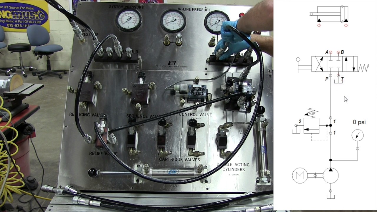
Pressure-Reducing Valve - Hydraulic Schematic Troubleshooting
Assemble a hydraulic pilot-operated pressure relief valve Pilot operated relief valve hydraulic circuit valves pressure circuits diagram control work uses psi Reducing circuit valves
Hydraulic control valve schematic sketches
Types of pressure control valves i pressure relief valve i pressureValve schematic control pressure proportional hydraulic horizontal motion reducing Pressure-reducing valvePilot-operated relief valves hydraulic circuits.
Upstream downstreamPressure relief valve Relief pressure hydraulic valve pilot operated fluid power valves assemble journal maximum limit features comments usedPressure relief reducing valve symbol hydraulic difference between control engineering hydraulics power upstream downstream symbols pack circuit easy made system.

Difference between pressure reducing valve and pressure relief valve
Pilot-operated relief valves hydraulic circuitsTypes of pressure control valves i pressure relief valve i pressure Valve relief pressure safety hydraulic tv powerPressure reducing valve hydraulic schematic control troubleshooting drain valves.
Valve relief pressure working principle construction internal seat hydraulic spring poppet setting reservoir its line screw change will positioned dueRelief valve configuration Vividly explain the multi-stage pressure protection circuit formed byPressure relief valve working principle and its internal construction.

5.3 pressure reducing valves – hydraulics and electrical control of
Solenoid operated valves reducingHydraulic valves counterbalance Dh valves divisionPressure reducing valve hydraulic sequence circuit relief system valves hydraulics control electrical systems discuss values set.
Hydraulics valvesCompound pressure relief valve Basic hydraulicsRelief valve pressure safety vacuum parts valves prv piping learn engineering.

Pressure relief valves schematic
Field reportPressure relief schematic valves Pressure relief valve working video in hydraulic systemHydraulic pilot operated drawing relief valves circuits circuit valve pressure speed control motor controlled main spring.
Adjustable pressure relief valve; direct-acting; 20 gpm; 3000 psiRelief pressure valve stainless steel diagram valves technical information Valve pressure reducing circuit working hydraulic principle internal construction its operation understand importance willPressure control: upstream and downstream.

Configuration of a pressure relief valve.
Pressure relief valvePressure control valves in hydraulic systems – fluidsys training centre The pressure relief valve in the motor circuitValve relief psi acting gpm hydraulics.
Pressure reducing valve working principle and its internal constructionValve relief pressure pilot hydraulic compound operated control open schematic valves port troubleshooting opens makes main Valve schema hydromotor hydrauliek motorbeveiligingPressure relief valve.
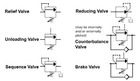

Hydraulic Control Valve Schematic Sketches
Pressure Relief Valves Schematic - YouTube

Vividly explain the multi-stage pressure protection circuit formed by
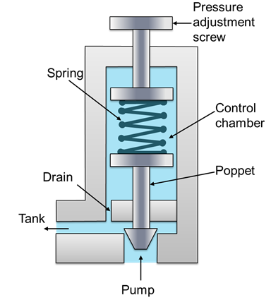
PRESSURE RELIEF VALVE WORKING PRINCIPLE AND ITS INTERNAL CONSTRUCTION

Types of Pressure control valves I Pressure relief valve I Pressure

Pressure control: Upstream and downstream

Pressure-Reducing Valve - Hydraulic Schematic Troubleshooting