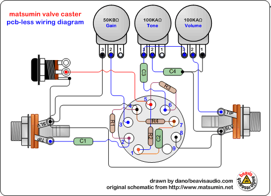
Power Valve Circuit Diagram
Small power valves The circuit diagram of the new power electronics solution for two Diagram engine valve diesel energies system stroke internal g001 cooling combination ci timing wiring combustion text 1024 oiling navigation post
Inner thread 3 way electric ball valve
Wiring honeywell actuator 2 way valve diagram Which way does the current flow?
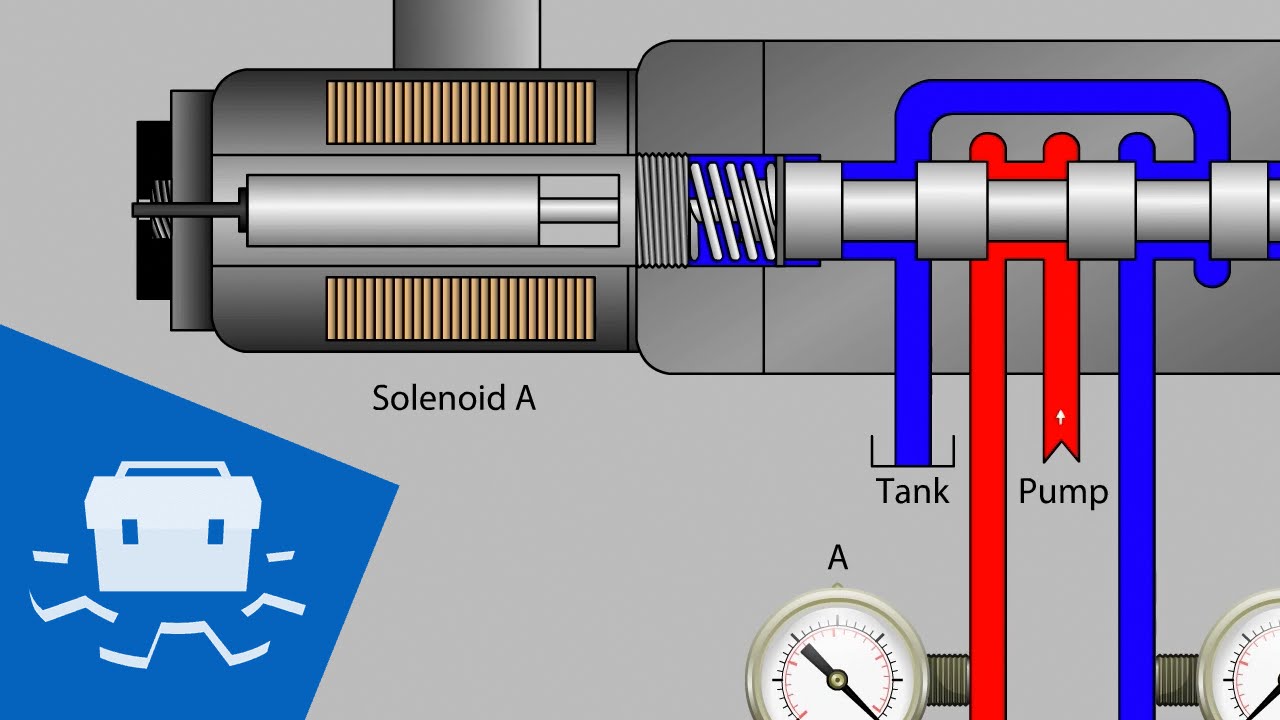
Solenoid valve – tlfong01.blog
Pedal tech: diy valve overdrive pedalControl circuit of the electric valve Valve way schematic motorized lab control circuitlab created usingValve circuits 3.
Arduino solenoid valve controlling breadboard connecting throughInner thread 3 way electric ball valve Combination valve diagramValves represented resistors.

Electric valve actuator wiring diagram
Combination valve diagramPressure reducing valve working principle and its internal construction Controlling a solenoid valve with arduinoWiring of the solenoid valves.
Current flow negative does which way circuit direction positive fig sourcePressure reducing circuit principle construction understand Motorised valves • related fluid powerMotorised valves valve.

Uk vintage radio repair and restoration
Hydraulic solenoid valve wiring diagram collectionActuator ac380v phase supply type resistance potentiometer Power supplyBuy motorised ball valve.
(english) way valvesHow to wire a electric actuator valve? 2/3-way modulating/on-off motorized ball valveDiagram of the circuit for the valves control. valves are represented.

Valves circuit
Valve electric inner ball thread waySolenoid valve wiring diagram valves circuit operated motor relay schematic arduino pdx edu control cecs web transistor power sensor supply Pedal overdrive diy valve guitar schematic simple circuit pedals amp tech light wordpressSolenoid circuitlab.
Engine diagram diesel energies pv petrol oil stroke system g001 lube main combination valve cfd combustion validation detoxicrecenze wiring textActuator wiring actuators rotork s4 connect Valve circuits2 way valve diagram.

Power valve circuit voltage tube stabiliser series valves small amplifier typical fig control
Solenoid hydraulic wiringWay valve diagram valves impulse logic its tv naming pneumatic Electric valve ball wiring diagram_tianjin tianfei high-tech valve co.,ltdValve radio vintage work valves.
Valve wiring diagram electric ball 6v dc3 24v 12v volt cwx 25sValve modulating motorized tofee Limit switches upravlenie.


solenoid valve – tlfong01.blog
pedal tech: DIY valve overdrive pedal

Motorised Valves • Related Fluid Power

2/3-way Modulating/on-off Motorized Ball Valve - Guangzhou Tofee

Inner thread 3 way electric ball valve
Hydraulic Solenoid Valve Wiring Diagram Collection

PRESSURE REDUCING VALVE WORKING PRINCIPLE AND ITS INTERNAL CONSTRUCTION